Introduction
Understanding how to calculate pump head is crucial for engineers and technicians working in various industries like water management, HVAC, and irrigation. Pump head, expressed in meters or feet, measures the resistance that a pump must overcome to move a fluid through a system's piping and components. This calculation ensures efficient system design and operation, optimizing energy consumption and prolonging equipment life.
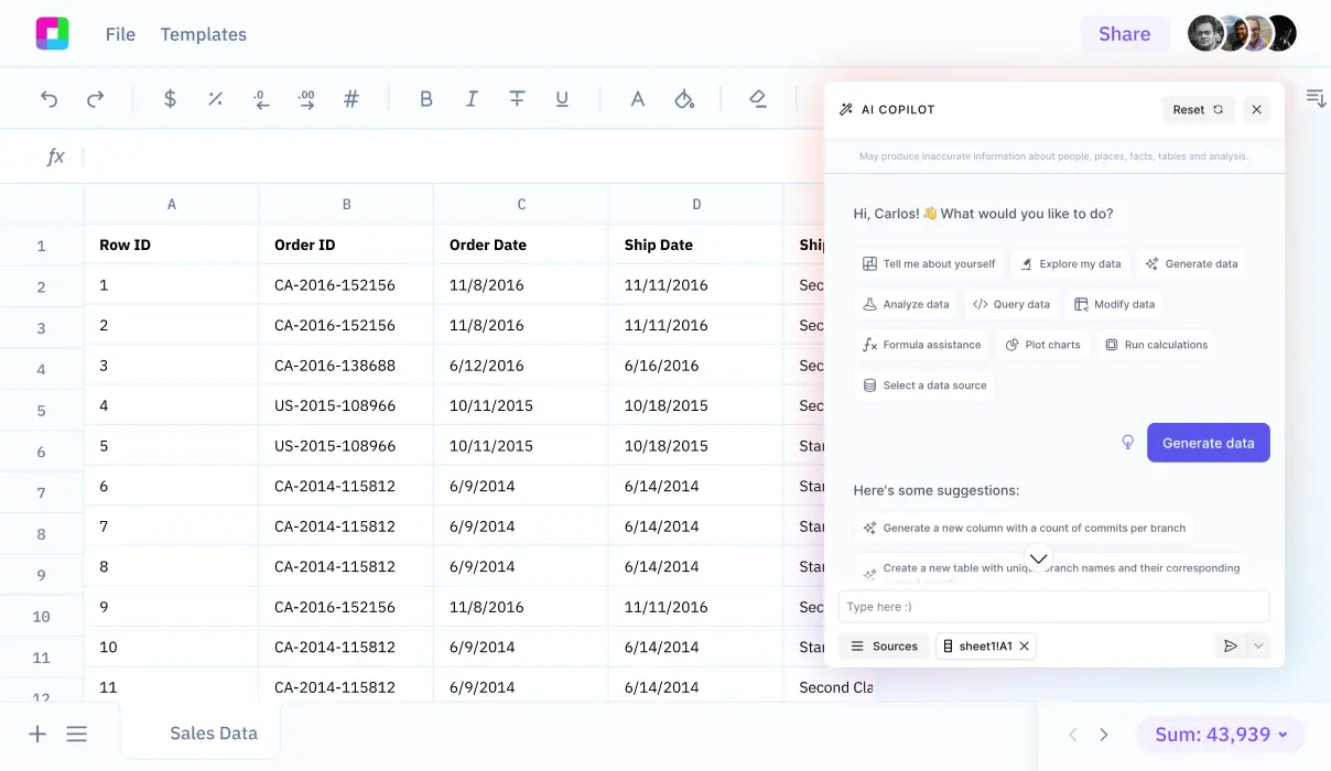
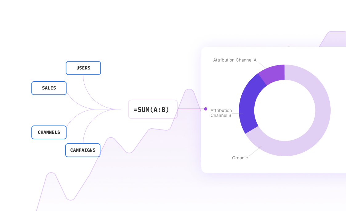
This guide will delve into the key components involved in calculating pump head, including static height, friction losses, and pressure requirements. Additionally, we will explore how Sourcetable's AI-powered spreadsheet assistant simplifies these complex calculations, making it an indispensable tool for professionals. Experience the ease of advanced calculations by signing up at app.sourcetable.cloud/signup.
How to Calculate Pump Head
Understanding the Basics of Pump Head Calculation
Pump head calculation is essential for designing and operating efficient pumping systems. It determines the energy delivered by a pump to transport fluid through a system. The fundamental formula used is Bernoulli's Equation: H1 + Hm = H2, where H1 is the inlet energy, Hm the energy added by the pump, and H2 the outlet energy.
Tools and Formulas Needed
To perform the calculation, utilize the Hazen-Williams model or apply the Bernoulli equation between the pump's inlet and outlet. The pump head itself is represented by Hm. Additionally, geodetic head Hg is calculated using Hg = h + Ha + Hb, incorporating suction head Ha, and delivery head Hb.
Calculating Distributed and Concentrated Head Losses
Head loss, a crucial factor affecting pump performance, is computed by adding distributed and concentrated losses. Distributed losses depend on pipe length and are calculated with Yc = (Fa/
Steps to Determine Total Pump Head
Begin by applying Bernoulli's principle. Define pressures P1 and P2 to compute Hg. Sum up the suction and delivery head losses to account for total head loss, thereby refining the pump head estimate. Remember, pump head is inversely proportional to flow rate; higher flow rates generally reduce head.
How to Calculate Pump Head
To accurately calculate pump head, apply the Bernoulli equation across the pump’s inlet and outlet. This method determines the energy, known as the pump head, that the pump imparts to the fluid. The formula used is H1 + Hm = H2, where Hm signifies the head added by the pump.
Step-by-Step Calculation
Begin by defining pressure terms P1 (inlet pressure) and P2 (outlet pressure) based on known quantities. Calculate gravitational head Hg using pressures P1 and P2. Subsequently, incorporate head losses from both the suction and delivery segments to address total head loss.
Account for Head Losses
Understand that head losses, which can significantly impact the pump head calculations, occur due to the fluid’s velocity and interactions with various pump components like valves and fittings. These losses are bifurcated into distributed (related to friction) and concentrated types. Calculate these using the appropriate friction factor and by taking into consideration both laminar and turbulent flow conditions.
Consider Flow Rate Impact
Remember that pump head is inversely related to flow rate; higher flow rates yield lower head and vice-versa. Adjust calculations according to the operational flow conditions to achieve accurate results.
By meticulously following these guidelines and accommodating for practical losses, professionals can effectively calculate and optimize pump performance to meet specific system requirements.
Examples of Calculating Pump Head
Example 1: Calculating Static Head
Determine the vertical distance water must travel in a system. This is straightforward: measure the height from the water source level to the discharge point. If the source is 10 meters below the pump and the discharge is 15 meters above it, calculate total static head: Static Head = 15m + 10m = 25m.
Example 2: Head Loss Due to Friction
To find head loss due to pipe friction, use the Darcy-Weisbach equation: h_f = f \cdot (L/D) \cdot (v^2/2g), where f is the friction factor, L is pipe length, D is diameter, v is fluid velocity, and g is gravitational acceleration. Assume a friction factor of 0.02, pipe length of 100 meters, diameter of 0.1 meters, and velocity of 1.5 m/s. Head loss calculates as: h_f = 0.02 * (100/0.1) * (1.5^2 / 2*9.81) ≈ 2.3m.
Example 3: Total Dynamic Head with Vertical Lift and Friction
To calculate the total dynamic head, add the static head and friction head loss. With a static head of 25m and friction head loss of 2.3m from the previous examples: Total Dynamic Head = Static Head + Friction Head Loss = 25m + 2.3m = 27.3m.
Example 4: Considering Minor Losses
Minor losses occur due to bends, valves, fittings, etc. These are often calculated as a percentage of the total dynamic head, commonly around 10%. For our calculated dynamic head of 27.3m, minor losses might be: Minor Losses = 0.10 * 27.3m = 2.73m. Thus, the adjusted total dynamic head would be: Total Dynamic Head with Minor Losses = 27.3m + 2.73m = 30.03m.
Example 5: Pump Head for a Closed Loop System
In a closed-loop system, only consider head losses since the static head is effectively zero (the starting and ending points are at the same level). Assuming the same friction head loss of 2.3m and minor losses of 2.73m: Total Head = Friction Head Loss + Minor Losses = 2.3m + 2.73m = 5.03m.
Discover the Power of Sourcetable for All Your Calculation Needs
Whether you're tackling school assignments, dealing with complex workplace computations, or simply indulging in personal projects, Sourcetable provides a seamless, AI-powered environment for all your calculations. Utilize Sourcetable’s AI assistant to harness effortless computational accuracy and versatility.
Efficient Calculation of Pump Head
Understanding head = \frac{P_2 - P_1}{ho g}, or the pump head, is essential for various engineering tasks. Sourcetable simplifies this critical calculation. Its AI digs into the depths of fluid mechanics and delivers precise, transparent results.
Whether you need a quick answer or an in-depth explanation, Sourcetable displays its computations in an intuitive spreadsheet format while providing a detailed step-by-step breakdown via its chat interface. This feature is not only vital for professionals in the field but also for students and educators seeking a clear understanding of the principles involved.
With Sourcetable, enhance productivity and ensure the accuracy of every calculation. Dive into a world where complexity is simplified, and learning is a continuous journey supported by advanced AI technology.
Use Cases for Calculating Pump Head
Pump Specification |
Calculating pump head using H1 + Hm = H2 is essential for specifying the correct pump. This ensures the selected pump can deliver the required energy to the fluid, accounting for inlet and outlet energies and actual energy delivered by the pump. |
Pump Sizing |
Effective pump head calculation allows for accurate pump sizing. This is critical during pump design, especially when pressures at the inlet (P1) and outlet (P2) must be derived using P1 = Pa - ρg * Ha and P2 = Pb + ρg * Hb to determine the appropriate pump dimensions. |
Flow Rate Determination |
By calculating pump head, engineers can determine the flow rate of the pump, facilitating optimal operation and efficiency. This is necessary to meet system requirements and ensure efficient fluid handling. |
Energy Assessment |
Determining the energy a pump can deliver to a fluid involves precise pump head calculations. This allows for evaluating system performance and energy consumption, influencing the selection process for energy-efficient pumps. |
Pump Performance Improvement |
Calculating pump head aids in assessing and enhancing pump performance. Addressing head loss, including friction and losses in valves and fittings, is vital for minimizing energy waste and improving overall efficiency. |
Total Head Determination |
Understanding the total head, which includes distributed and concentrated losses, is crucial for system design and troubleshooting. This helps in ensuring the system functions as intended without excessive energy expenditure. |
Frequently Asked Questions
What is the basic principle used to calculate pump head?
The basic principle used to calculate pump head is the Bernoulli equation, which measures the energy at the pump's inlet and outlet to determine the head.
How do you calculate pump head using the Bernoulli equation?
To calculate pump head using the Bernoulli equation, set H1 as the inlet energy, Hm as the energy delivered by the pump, and H2 as the outlet energy. Use the equation H1 + Hm = H2 to find the head.
What factors should be considered when calculating pump head?
When calculating pump head, consider the head loss that occurs due to friction in the pipes and in various construction parts like valves and curves, as these reduce the pump's effective head.
How does flow rate affect pump head?
Pump head is inversely correlated with flow rate. The higher the flow rate, the lower the pump head, and vice versa. This is because the energy available to lift the fluid decreases as the flow rate increases.
Conclusion
Calculating pump head, an essential measure for assessing a pump's capacity to move fluids against gravitational forces, involves key factors such as flow rate, vertical lift, and friction losses. Pump head calculation, expressed as P = ρgh + hf, where ρ is the fluid density, g is gravity, h is the height, and hf are the friction losses, requires precision for optimal system performance.
Experience Ease with Sourcetable
Sourcetable, an AI-powered spreadsheet tool, significantly streamlines these vital calculations. Designed to manage and simplify data-intensive tasks, Sourcetable allows you to easily input data, perform calculations, and analyze results efficiently. The platform is incredibly user-friendly, making it perfect for both professionals and those new to hydraulic calculations.
Apply the principles of pump head calculation using Sourcetable's robust capabilities to ensure accurate and effective results. You can experiment, modify, and perfect your calculations with the aid of AI-generated data, enhancing your fluid dynamics projects' reliability and success. For those interested in exploring the power of automated calculations and data management, visit app.sourcetable.cloud/signup to try Sourcetable for free.


